*How to identify the value of the location 0240 on the EEPROM

Replace the backlight placed under the original LCD with the one supplied with the Minitools part to avoid chromatic discrepancies. To watch it, click on the button below.
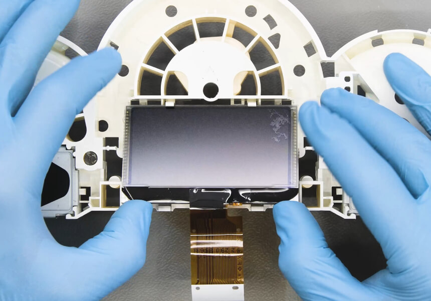
Remove the original display.

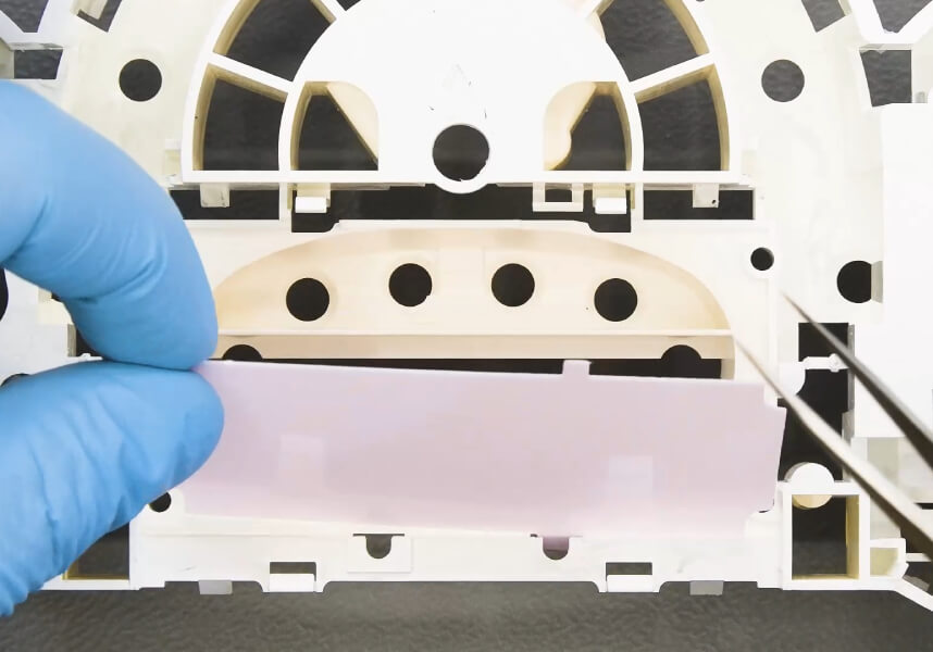
Undo and remove the diffuser and the pink original backlight.


Fit and secure the new Minitools backlight.

Re-insert the diffuser.

Fit the new Minitools display
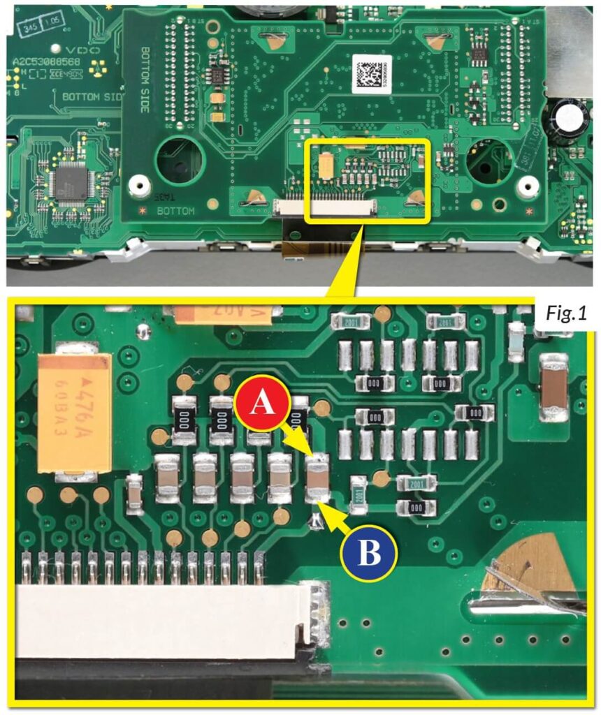
After replacing the LCD, switch on the cluster (pin nº 1 negative, pin nº 2 positive) and, with a multimeter, measure the voltage on the PCB on which the display is connected, between the points A and B indicated in picture 1.
NOTE: For this modification it is necessary to use an EEPROM programmer. We recommend our SEP-EECLIP.
• First, set the programmer reading in 8 bit hexadecimal (HEX) .
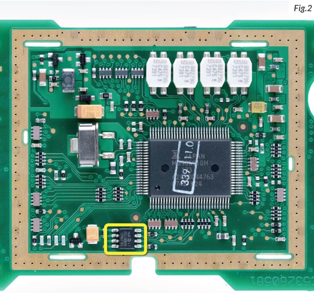
• De-solder the 93LC86 EEPROM (highlighted in picture 2), which is located inside the metal enclosure on the rear side of the display PCB.
• ATTENTION: Make a backup of the de-soldered EEPROM, before the modification.
• To reach a voltage between 11,95V and 12,05V, it is necessary to modify the value of the location 0240. Please note that decreasing these locations by 1 HEX unit, the variation will be +0,00625V, or vice versa.
If not familiar with hexadecimal calculation, it is possible to use the calculation tool in the box beside, simply typing in the values.

Once these modifications have been done, measure again the voltage between the points A and B and check that it actually is between 11,95V and 12,05V. If not, increase or decrease the location until the value is as close as possible to the correct range.