- 01/02/2021
GUIDE FOR CITROËN, FIAT, LANCIA, PEUGEOT AND TOYOTA MULTIFUNCTION DISPLAY REPLACEMENT
Citroën Berlingo, C3, C4, C5, C8, Jumpy, Fiat Scudo, Ulysse, Lancia Phedra, Peugeot 206, 207, 3008, 307, 407, 508, 807, Expert, Partner, RCZ and Toyota Proace multifunction module LCD pixel repair
Is the Citroën C3 multifunction unit display difficult to read? Is the Peugeot Partner multifunction module display not working? Is the Citroën Berlingo multifunction unit display malfunctioning? Does the Peugeot 407 multifunction module display have faulty pixels? Is the Citroën C8 multifunction dashboard display fading?
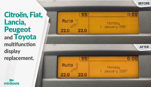
The following guide will explain how to repair the Johnson Controls and Borg multifunction unit of several Citroen, Fiat, Lancia and Peugeot models, replacing the fading or defective display with Minitools part SEPDISP29P.
N.B. The SEPDISP29P is a positive version display, it is important to check the exact model, comparing the other displays available on our store: : SEPDISP29N (negative version); SEPDISP28N (negative version) and SEPDISP28P (positive version). Click here for the comparison sheet
Unhook the module metal frame by levering on the side catches.
Then, remove the plastic backing.
Release the board with the display.
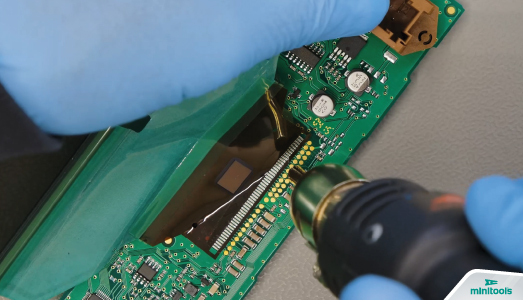
De-solder the original display with a hot air de-soldering iron.
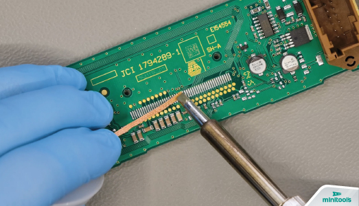
Using a soldering iron with chisel tip and de-soldering braid, remove any residual solder. Clean with some solvent.
Position the PCB of the new Minitools display matching the board contacts, leaving a 1 mm gap.
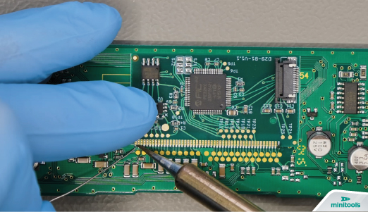
With a soldering iron with needle tip, fix the PCB in several spots and solder it pin by pin.
Clean with some solvent.
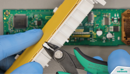
With a flush cutter, cut the central catch from the plastic part where the LCD is placed.
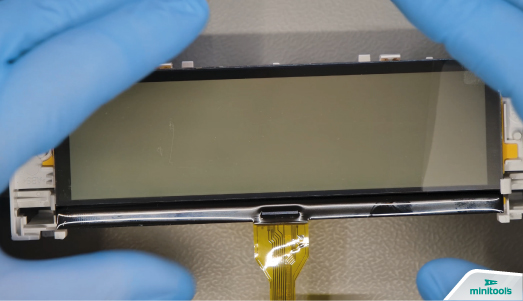
Remove the film from the back of the new display and fit it in its place. Fit the board as well.
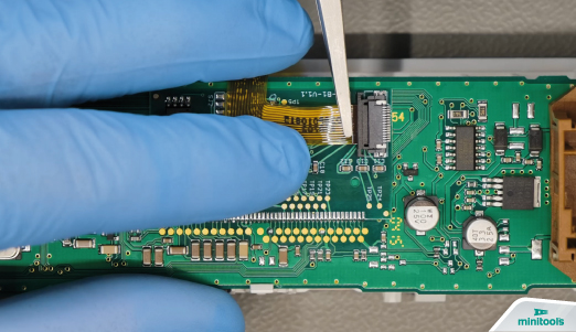
With the aid of the tweezers, insert the Minitools displays FPC in the appropriate connector placed on the PCB and secure it.
Re-fit the module in the back cover.
Remove the front protective film and fit the metal frame.
Re-install the unit in the car.
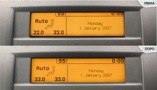
If the information looks slightly cut on the top part and a dark line appears in the bottom one (see gallery), file the side holes of the modules as shown in the tutorial below to allow a correct placement.
Perfetto! Problem solved!
CAN BUS interface to power up the unit before re-installing it in the car available (SEP-CAN-INFO1).