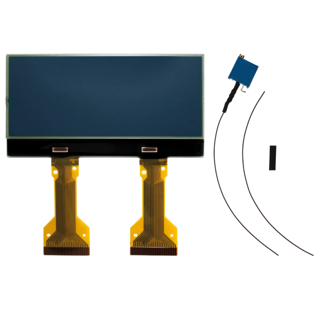
supplied with modification kit
Before installing the new SEPDISP04 display, please read the following instructions carefully. DO NOT SKIP ANY STEPS.
After installing the new Minitools display, switch on the infocenter (pic. 1) and check that the information shown is sharp as in pic. 2.
If not, follow all steps at section “ALFA ROMEO 156 INFOCENTER “.
After installing the new Minitools display, switch on the sat-nav (pic. 3) and check that the information shown is sharp as in pic. 4.
If not, follow all steps at section “ALFA ROMEO 147 SET NAV“
NOTE: For ALFA ROMEO 147 CAR RADIO/SAT NAV, click here.
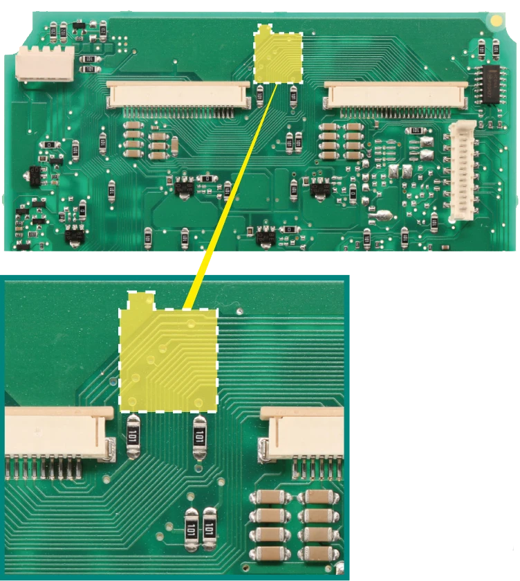
Remove the Minitools display and the resistor highlighted in picture 5.
Position the trimmer (supplied with the kit) in the area indicated in picture 6, securing it with the double-sided adhesive tape on its back.
Solder trimmer terminal 3 to point A (GND) (pic.7) and install a jumper between terminal 2 and point B, placed on the back of the board (pic. 8).
Reconnect the Minitools display as in picture 9 and switch on the infocenter (pic. 10).
While the module is on, act on the trimmer wheel to adjust the display visualization.
Check if the display is sharp.
If not, act again on the trimmer wheel until the required sharpness is reached.
NOTE: Fot ALFA ROMEO 156 INFOCENTER, click here.
Remove the Minitools display and the resistor highlighted in picture 11.
Solder the cable supplied with the kit (picture 12) to terminal 3 of the trimmer and insulate with its heat shrink sleeve.
Position the trimmer in the area shown in picture 13 and secure it with the double-sided adhesive tape on the back.
Connect two jumpers, one between terminal 2 and point C and the other between terminal 3 and point D (pic. 4).
Reconnect the Minitools display and switch on the sat-nav (picture 15).