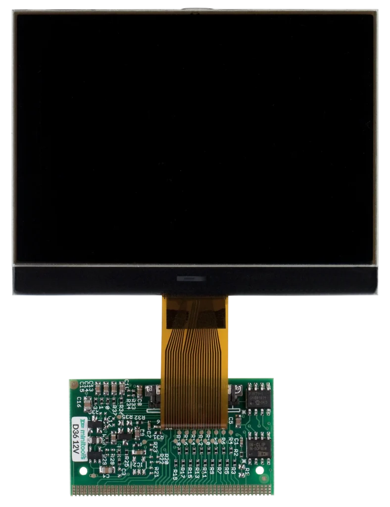
SEPDISP36
Installation instructions
The SEPDISP36 display is adaptable to VDO and Jaeger/Marelli instrument clusters.
1
WARNING
Before installing the SEPDISP36 display, please read carefully the following instructions. For illustrative purposes, our technicians have produced a video tutorial about how to repair the instrument clusters. To watch it, click the button below.
DO NOT SKIP ANY STEPS.
2
Some supported car models
• Audi A2 (2000 – 2005);
• Audi A3 (VDO / Jaeger 1996 – 2003);
• Audi A4 (VDO / Jaeger 1994 – 2001);
• Audi A6 (VDO / Jaeger 1997 – 2004);
• Audi S4 (VDO / Jaeger 1997 – 2001);
• Audi RS4 (VDO / Jaeger 1999 – 2001);
• Audi S6 (VDO / Jaeger 1999 – 2003);
• Audi RS6(VDO / Jaeger 2002 – 2004);
• Audi TT (1998 – 2006);
• Ford Galaxy (2000 – 2006);
• Seat Alhambra (2000 – 2010);
• Seat Ibiza/Leon (up to 2004);
• Volkswagen Bora (1998 – 2005);
• Volkswagen Golf IV (1997 – 2003);
• Volkswagen Passat (1996 – 2002);
• Volkswagen Sharan (2000 – 2010);
• Volkswagen Transporter T4 VDO (1998 – 2003).
• Volkswagen Transporter T5 VDO (2003- 2009).
Note: partial list
3
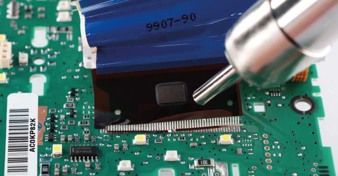
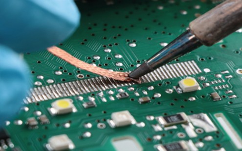
After desoldering the original display, clean the contacts with a desoldering braid to remove excess solder. Flux can be used.
4
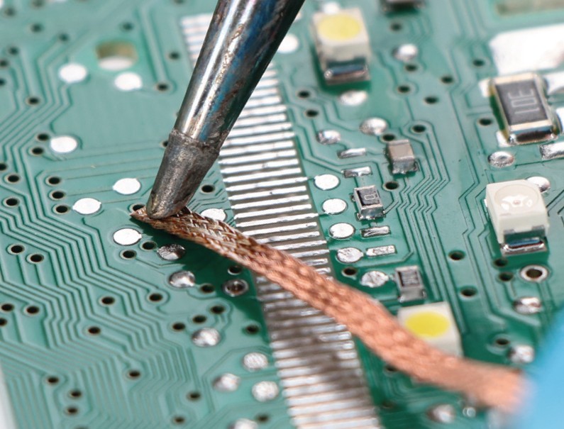
Clean any excess solder off the pads to prevent the PCB from being lifted.
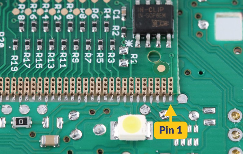
Place the PCB on the circuit, starting from pin 1 at the bottom right.
5
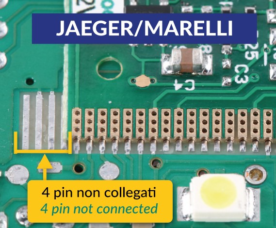
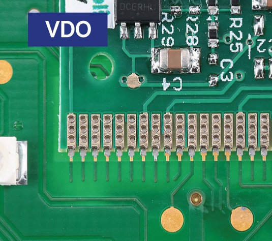
For Jaeger/Marelli instrument clusters only, the 4 pins on the left won’t be connected.
For VDO instrument clusters, all pins will be connected.
6
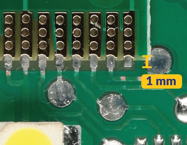
Leave 1 mm gap.
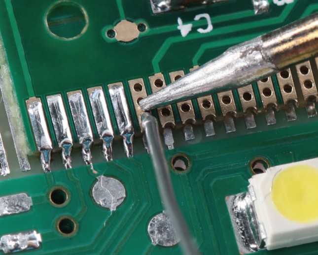
Solder each pin, one at a time, with 0.3 mm tin solder wire and needle tip. Don’t use flux. After soldering the small board, clean with a suitable solvent.
7
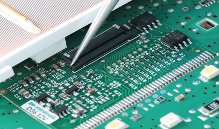
Open the PCB connector by levering on both ends, then insert the new LCD FPC.
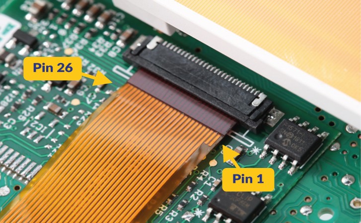
Insert the FPC of the new display into the connector of the PCB. Pin 1 must be on the right (see photo).
8
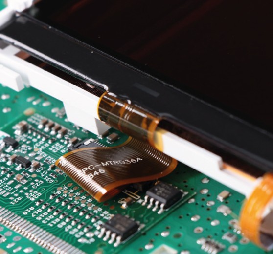
Position the FPC folding it under the display. Ensure the plastic parts of the
instrument cluster do not compress the FPC once it has been refitted. If this happens, try repositioning it.
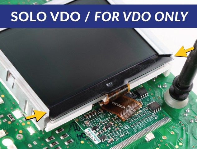
Before positioning the metal frame, cut it at both points as indicated (see photo). The frame could damage the display if this procedure is not followed.
9
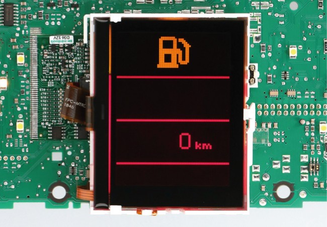
Switch on the dashboard with the Minitools connector SEP-PA003.
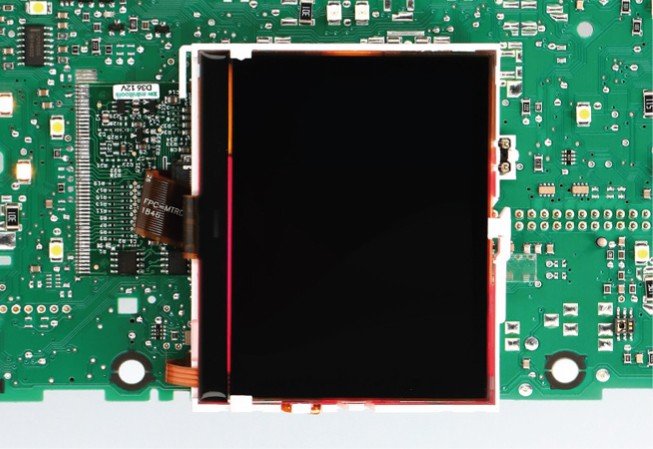
If the display stays off, read the following instructions.
10
PROBLEMS AND SOLUTIONS
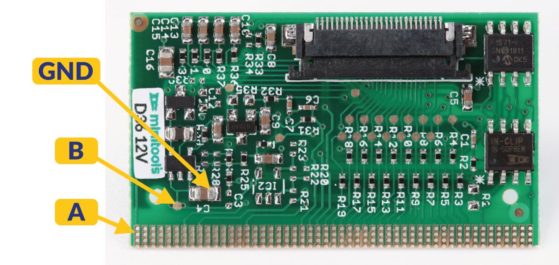
Check that the voltage between points A and GND is between 11,5V and 12,5V. Check that the voltage between points B and GND is at least 4,5V. If not, double check all solderings done.
FOR VDO CLUSTERS ONLY: if the voltage between points B and GND is not at least 4.5V, follow the instructions at step 11.
11
PROBLEMS AND SOLUTIONS - For VDO dashboards only
If the voltage between B and GND isn’t at least 4.5V (see step 10) install a jumper between point B on the PCB and pin 8 of the Eeprom 93C66 located on the main board of the cluster (see picture on the right).
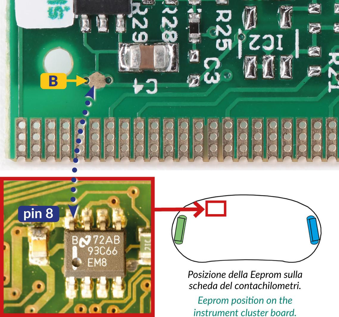
If the problem persists, take a picture of the PCB assembled and
send it to [email protected]
